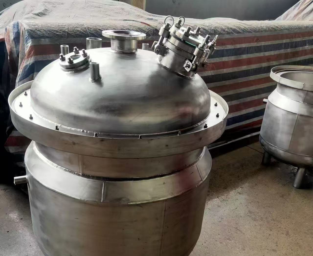
Reactor lining failures trace back to six causes: thermal shock beyond the stated limits of cold shock ≤ 110 °C and heat shock ≤ 120 °C, mechanical impact, agitator contact, attack by media the lining is not rated for, voids or thin spots in the coating, and stress at the jacket, nozzles and cover clamps. The media the lining cannot take are specific: hydrofluoric acid, fluoride-bearing solutions, phosphoric acid at 30 % or above when the temperature is over 180 °C, and strong alkali above pH 12 at 100 °C. The shape and location of the damage name the cause before you send a single sample away.
1. Thermal shock: the 110 °C and 120 °C limits are hard limits
A glass lining is glass. It has a lower expansion coefficient than the steel it is bonded to, so every temperature step puts the two under shear. The limits are cold shock ≤ 110 °C and heat shock ≤ 120 °C, and they apply to the step, not to the operating temperature on the specification sheet.
The classic failure is a cold charge into a hot vessel: 20 °C solvent into a vessel at 140 °C is a 120 °C step before the agitator has turned once. Steam into a cold jacket does the same thing from the other side, and so does a cold wash hitting a hot bottom outlet.
On site it looks like a fine map of hairline cracks with no depth, most often around the bottom outlet, on the jacket side of the inner wall, or wherever the step landed first. If the cracks show only under a torch, it is thermal. Bring the vessel up and down in stages, use warm wash water, and write the limits into the batch sheet in °C rather than as "hot" and "cold".
2. Mechanical impact: shovels, clamps and pressure jets
Charging solids over the manway rim, a steel shovel scraping the wall, a dropped swing clamp, a high-pressure jet on a stuck cake. The result is a dished crater with bare steel at the centre and star cracks radiating outward, usually on the shell at manway height.
The rules are plain. Charge through a chute, not over the rim. Use wooden or PTFE tools, never a wire brush or a metal scraper. No pressure jetting on the lined surface. A lining damaged at one point can be repaired, but only once the tool that did it has left the building.
3. Agitator and baffle contact: the failure that repeats
A bent shaft, a worn bearing, the wrong impeller diameter, or a baffle that has worked loose gives you a clean score line at one height, or a circular track on the bottom head. It is mechanical, it happens every batch, and it will be in exactly the same place after a repair.
Before blaming the lining, measure shaft runout and impeller-to-wall clearance with the vessel empty. A dial gauge and an hour settle the question; a failed lining does not.
4. Chemical attack outside the media envelope
The lining handles inorganic and organic acids, organic solvents and weak bases at various concentrations. It does not handle hydrofluoric acid, fluoride-bearing media, phosphoric acid at 30 % or above above 180 °C, or strong alkali above pH 12 at 100 °C. Read those last two as combinations of concentration, pH and temperature, not as single numbers.
Chemical damage looks different from thermal or mechanical: gloss loss over a wide area, an orange-peel or dark etched surface, flaking that follows the liquid line or a weld seam instead of forming a circle. If the pattern sits where the liquid sits, it is chemistry.
Fluoride is the one that catches people. It arrives in a raw material certificate, in a catalyst, or in a cleaning agent, at a concentration nobody flagged. Check the incoming assay before you blame the vessel.
5. Pinholes, thin spots and repairs
Not every failure is the process. A pinhole at a weld, a thin spot on a nozzle neck or a patch applied during fabrication will fail on its own schedule. That is what the high-voltage test is for: the test voltage in kV is set against the lining thickness in mm, and both should appear on the record as numbers.
Ask for the test record and the thickness measurement with the vessel documents, not after the first leak. On any repair, record the location, the area in cm² and the method. A repaired lining is not an original lining, and whoever operates that vessel next deserves to know.
6. Jacket, nozzle and clamp stress
The steel shell expands more than the glass on it. Steam in the jacket, a hot nozzle, or an unsupported pipe run hanging on a lined connection all put bending stress into the coating. Cracks that start at a nozzle neck or radiate from the manway seating face are usually this.
An open Type K vessel with a removable cover is opened far more often than a closed Type F with an integral head, so its clamp face sees more load cycles. Two habits fix most of it: torque the cover clamps in a cross pattern with a torque wrench, and support the pipework independently of the vessel. A clamp tightened until it feels right loads one side of the lining.
Reading the damage on site: four questions
Before you clean the area, photograph it with a scale and run a holiday test to find the true boundary of the damage. Then ask:
- Where is it? Bottom outlet and jacket-side wall points to thermal. Manway height on the shell points to impact. One height on the wall, or a circular track on the head, points to the agitator. Nozzle neck or manway face points to stress. Following the liquid line points to chemistry.
- What shape is it? Hairline map is thermal. Crater with bare steel is impact. Clean score is mechanical. Broad etch or gloss loss is chemical. Crack radiating from a weld is stress.
- What changed? Read the batch record, the wash record and the temperature log for the last ten batches. The failure date is usually the date of a new raw material or a new operator.
- Has it happened here before? Damage in the same place after a repair means the cause was never removed, and repairing it again will give the same result.
A lining failure is evidence, not bad luck. The location and the shape name the cause, and the cause is usually in the process or the operating procedure rather than in the glass.
What to do next
Three things, in order. Get the numbers with the vessel: high-voltage test in kV, lining thickness in mm, and the thermal shock limits — cold ≤ 110 °C, heat ≤ 120 °C — written into the operating procedure. We collect and check these during pre-shipment inspection in China, and you should have them before the crate is opened, not after the first leak.
Second, put the six causes on one page next to the reactor and log every event: charge, wash, temperature step, repair. A log showing a 130 °C step two days before the leak ends the argument with the supplier, the operator and the insurer.
Third, if the damage sits at a nozzle, a clamp face or a baffle fixing, treat it as a specification problem and take it back to the drawing. The specification confirmation sheet you approve before fabrication is where that gets corrected, and a change there costs a revision rather than a shutdown.